Techical Specification

Prime a branch which represent quality & reliability giving the customer confidence and comfort. Prime offers products that meet demanding international manufacturing and safety standards. Our safety shoes manufactured as per IS-15298 standards and certified by CLI(Central Labor Institute)& FDDI.
| Penetration resistant sole | |
| Energy absorbing heel | |
| Electrical resistant sole | |
| Anti-static & conductive sole | |
| Heat resistance sole | |
| Water resistant upper(As special requirement) | |
| Oil resistant sole | |
| Cut resistant upper | |
| Impact protection |
Laboratory
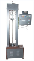
UNIVERSAL TENSIAL TESTING MACHINE [FOR LEATHER]Leather tensile and tear strength test machine. 1.Cut the test piece with cutting dyes. 2.Measure the thickness of upper. 3.The maximum thickness is about 1.8 to 2.0 mm. 4.The thickness is measured with the help of measuring gauge. 5.In accordance with the IS 03376 the minimum force of tensile strength-15 N/mm². Tensile strength=R1÷R2×5 R1-direct reading R2-thickness of upper 5-constant width of upper 6.In accordance with IS 03377 the force for tear strength-120N. Result:After testing of tensile and tear strength are more than 15 N/mm² and 120N.
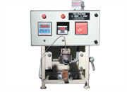
HEAT RESISTANCE TESTING MACHINE [FOR SOLE] Nitrile Rubber sole test for 300°C temp. 1.Take an out sole of tested piece. 2.Cut away heel portion. 3.Place the test piece on platform below with its wear side uppermost. 4.Move the insulating support aside and immediately place bit centrally on the test piece. 5.Leave it position in for 60 seconds. 6.Remove the foil allow the test piece to cool for at least 10 min. Result:Examine the heated portion visually not damaged such as melting,charring,cracking,so it is accepted.
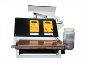
ANTISTATIC PROPERTY TESTING MACHINE [FOR SHOE] Use for complete shoe test. The purpose of this footwear is to ensure the discharge of emf developed in the human body. The application of this type of footwear is to avoid the incidence due to sparking which may cause in the premises of explosive and inflammable material like paint shop,armed explosives and petroleum products. To confirm the above property the requirement as per IS 15298 part1 2002 are as follows: The electrical resistance shall be within the limit of 100 KΩ minimum to 1000 MΩ maximum. The IS standard suggests that these tests are to be carried out periodically to confirm this property.
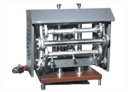
BENEWART FLEX TESTING MACHINE [FOR SOLE] Use for sole test. 1.Take an out sole of tested piece. 2.Cut away heel portion. 3.Pierce between sole cleat at 3 points,along the maximum bending stress(twice in the edge zone of the sole 10 mm from the edge and once in middle.) 4.Measure the length of slit. 5.Clamp the spcimen and carry out 30,000 flexing cycle. 6.Remove the sample and measure the cut growth and note it. 7.Store the tested specimen for 6 months with identification. Result:After completion of 30,000 flexing cycle cut growth not more than 4mm,so it is accepted.
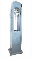
IMPACT TESTING MACHINE [FOR STEEL TOE] Use for steel toe ckecking. 1.Testing procedure followed by IS-15298(Part-1)2002. 2.Position a Cylinder with the centre of the cylinder on the test axis. 3.Let the striker to drop on the test axis from the appropriate height to give on impact energy of (200 ± 4)J,for toecaps to be used for safety footwear. 4.And (100 ± 2)J,for toecaps to be used in protective footwear. 5.Measure the nearest 0.5mm,height to which the cylinder has been compressed. Result:This value is the clerance at the moment of impact.
| Minimum clearance in mm | |||
| Size | MM | Size | MM |
| UP to 3 | 12.5 | 7 and 8 | 14.0 |
| 4 and 5 | 13.0 | 9 and 10 | 14.5 |
| 6 | 13.5 | 11 and above | 15.0 |
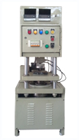
COMPRESSION AND PENETRATION RESISTANCE MACHINEUse for steel toe and sole test. COMPRESSION RESISTANCE MACHINE 1.Position a cylinder inside the test piece centre of the cylinder on the test axis. 2.Position the clamping device & test piece between the platens of the compression machine. 3.Compress the test specimen to a load 15 ± 0.1 KN for safety footwear & 10 ± 0.1 KN for protective footwear, & move at a speed of 5 ± 2 mm/min. 4.Measure the nearest 0.5 mm, height to which the cylinder has been compressed within 10 mm of the impression of toe cap by using the dial gauge. Result:This value is the compression clearance.
| Minimum clearance in mm | |||
| Size | MM | Size | MM |
| UP to 3 | 12.5 | 7 and 8 | 14.0 |
| 4 and 5 | 13.0 | 9 and 10 | 14.5 |
| 6 | 13.5 | 11 and above | 15.0 |
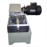
WATER PENETRATION AND WATER ABSORBENTCalculate the percentage gain in mass of the test piece. FOR PENETRATION 1.Cut a rectangle test piece (75x60mm) from the upper & buff the wear surface lightly by rubbing with a grade 180 emery paper & condition for 48 hour at 20 ± 2°C & 65 ± 5% RH. 2.Adjust the apparatus to give an amplitude of 3mm (7.5% compression of the test piece). 3.Weigh the test piece to the nearest 0.001gm and record its mass m1. 4.Fix the test piece in the apparatus, with the wear surface outside to make a trough of 60 mm length, 10 mm overlapping on each cylinder. 5.Put the brass turnings into the trough, lower the plate electrode to make contact with them & connect the electric circuit. 6.Raise the level of water in the tank until the water lies 10 mm below the top of the cylinders. 7.Start motor & measure the time interval until water first penetrates through the test piece, as indicated by a signal from the electric circuit. 8.After 60 min from the start of the test, stop the motor & remove the plate electrode & brass turnings. remove the test piece, blotting lightly to remove adhering moisture & reweigh, record its mass m2. 9.Calculate water penetration from the equation. Water penetration - pw in gms. pw = m2-m1 where m1= initial mass of absorbent cloth in gm. m2= final mass of absorbent cloth in gm. FOR ABSORBENT 1.Weigh the cloth & record its mass m1.size 120x40mm witha mass of @ 300 g/m². 2.Roll it to from a cylinder of length 40mm & place it in the trough. 3.Replace the plate electrode (the roll of absorbent cloth applies a load 1to 2 n) so that it rest on the cloth & restart the motor. 4.After 30min, stop the motor; remove the cloth,(if necessary mopping up any surplus water within the trough) reweigh, record its mass m2. 5.Calculate water absorption from the equation. Water absorbent - aw, percentage by mass. aw = m2 - m1 ÷ m1 × 100% where m1= initial mass of the test piece gm. m2= final mass of the test piece gm.
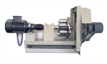
WATER VAPOUR PERMEABILITY AND WATER VAPOUR COEFFICIENTTo determine the mass of moisture of test piece and been absorbed by the desiccant. 1.Cut a test sample 70×45mm dimension & carry out 20,000 cycles of flexing .Then cut a circular test piece of diameter 34 mm centrally at which the flexing creases meet. 2.Half fill a jar with regenerated silica gel. 3.Fix the test piece over the opening of the jar & start on its motor. 4.Carry out the test in a strong current of air, produced by the fan. 5.After more than 16 hour stop the motor & remove the first jar. 6.Half fill the second jar with silica gel and fit the test piece on second jar from first jar. 7.Weight the second jar with test piece & silica gel, mass m1. fit the jar in holder & start the motor. 8.After 7 hour stop the motor & reweigh the jar, mass m2. 9.Calculate the results from equation.
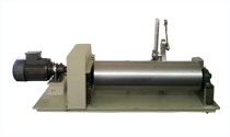
ABRASSION RESISTANCE OF OUT SOLE 1.Take an outsole of test piece. 2.Cut away test piece from heel portion or toe portion, which ever is suitable. 3.Note the weight of test piece - W1. 4.Clamp the test piece on machine. 5.Start the drum type machine to achieve specified linear movement. 6.Remove the test piece & note the weight of test piece as - W2. 7.Calculate the weight loss due to abrasion as W1 - W2 = W3. 8.Calculate the abrasion resistance. 9.Store the specimen for six month for identification.
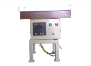
INSULATION AGAINST HEAT 1.Take the complete item of footwear as the test piece. 2.Condition the test piece for 7 days at 20 ± 2°C & 65 ± 5% RH. 3.Fix the thermocouple to the insole in the center ofthe joint area & place the steel balls inside the footwear. 4.Take the conditioned test piece & carry out the test under ambient conditions of 20 ± 2°C 5.Set the temp. of the hot plate to 150°C & place the test piece on it with sand. 6.Use the temp. measuring device connected to the thermocouple & measure the temp. on the insole as a function of time. 7.Record the temp. increase graphically. 8.Calculate the nearest 0.5°C, the increase in temp. after 30 min. from the time the test piece was placed on the sand bath.


 Copyright (c) 2013. All rights reserved By Prime Shoes.